SICK experts are often asked to advise on the selection of a safety laser scanner as there are many to choose from and they all have different technical specifications. It is common for people to simply want the "biggest". But in the following article we try to explain that in mobile applications, this is not the only value to consider.
The perfect size of the protective field on an industrial autonomous vehicle
The maximum protective field that a scanner can facilitate is an important feature but this value alone should not be a deciding factor on whether the scanner is suitable for an industrial autonomous vehicle application. I explore how the response time of your safety devices and control system together can dramatically affect the size of a protective field required and how this directly affects applications.
It must be pointed out that there are lots of things that need to be considered on an industrial autonomous vehicle application, such as the environment, breaking system etc. and that a full comprehensive risk assessment should be carried out by the designer. Any information in the article is simply a guide and cannot be used to constitute agreement on any hazards, exclude unrecognised hazards or confirm the degree of harm relating to any such hazards in any real applications. This would remain the responsibility of the designer/manufacturer of any such equipment.
History of safety laser scanner
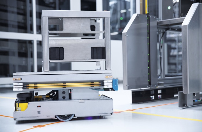
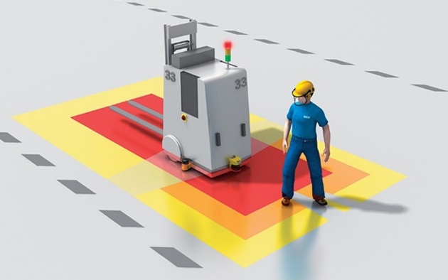
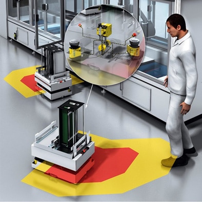
The safety laser scanner has played a key role in development of automated systems since the introduction of the “Optotrap”, which was the first Category 2 area scanner, released by SICK in 1976. Following this, 1994 saw the release of the first category 3 safety laser scanner by SICK, and since then these devices have facilitated more productive and efficient manufacturing as well as improving safety at work. One impressive example is in the automated guided vehicles (AGVs) market where safety laser scanners have single-handedly enabled them to move at greater speeds by replacing bump strips. A bump strip is a contact sensor and, when used, in order that an AGV can stop safely without causing injury, it must move at a sufficiently slow speed so that it can react in time. Safety laser scanners allowed the safe non-contact detection of personnel and obstructions far ahead of their path, allowing much faster speeds, figure 1.
Safety laser scanner type
A safety laser scanner is a Type 3 device, the requirements of which, are contained in the harmonized standard EN 61496-1. When a safety function includes a Type 3 safety laser scanner, the maximum performance level (PL) or safety integrity level (SIL) that can be achieved is PLd (EN ISO 13849) or SIL2 (IEC 62061). There is also a technical specification for safety laser scanners, IEC 61496-3, which covers the particular requirements for Active Opto-Electric Protective Devices responsive to Diffuse Reflection (AOPDDR).
Used in both stationary and mobile applications, they can trigger a machine or vehicle to safely slow down or stop as soon as they detect a person, part of a body, or an unexpected obstacle inside the protective field.
Time-of-flight measurement principle
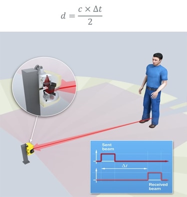
Safety laser scanners use the time-of-flight measurement principle in which a pulse of light is transmitted, reflected and then detected. The distance (d) from the object to the scanner is worked out using the time taken for the beam to return (ΔT) and the speed of light (c = 3 x 10⁸ m/s ), figure 2.
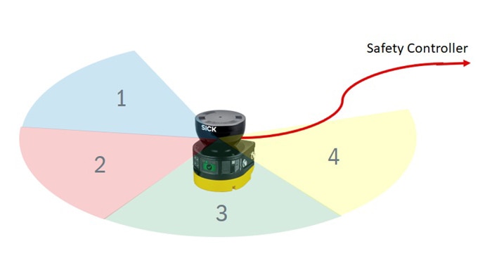
A mirror inside the scanner rotates this beam around allowing measurements around a radius in a plane. This means that the scanner can build up a profile of the surrounding area and operating entities can configure different fields in the scanner that can be used to turn different outputs on and off for use in safety functions. Some scanners may also be used in multiple safety functions due to their capability of being able to simultaneously evaluate multiple fields at the same time, figure 3.
Simultaneous field evaluation enables complex applications to be solved that have proven difficult in the past due to the limitations of the number of outputs being just one or maybe two (OSSD’s).
Types of Field
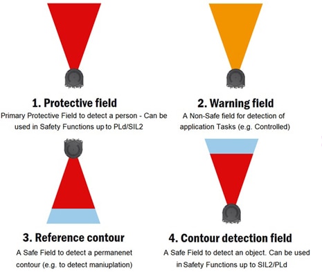
There are four types of field defined for a safety laser scanner, figure 4.
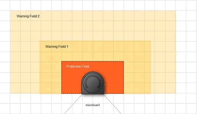
Additionally, a combination of these fields can be combined to form a “field set”, figure 5.
Safety laser scanners have the facility to store many field sets each of which is chosen based on a set of input conditions, which normally come in the form of:
• Hardwired inputs
• Software bits
• Speed information from encoders
Each particular condition which defines which field set is selected is called a “monitoring case” which contains the field set, the inputs conditions and may also contain information such as the “multiple sampling”, which I will discuss further below.
It is important to mention here that switching between cases adds to the response time of a system which is why it is sometimes popular to use simultaneous field evaluation (Looking at multiple protective fields in one field set at the same time) to keep the response time down.
Multiple sampling
By default, a safety laser scanner must see an object twice in a row (two revolutions) in order that an object is safely detected. In difficult environments and based on the scanners detection robustness this can be too sensitive and can cause problems due to detection of dirt, dust, welding sparks or vibration affects. The multiple sampling value can increase the number of times an object needs to be seen before a detection signal is created which can dramatically increase the availability of a system. For example, if a multiple sampling of 3 is configured on a protective field that is routed to OSSD’s, an object must be detected in the protective field three times in succession before the OSSD’s switch OFF.
However, there is a trade-off using this feature since the total response time is increased for every extra scan and this can have adverse consequences in AGV applications.
Automated Guided Vehicles
When integrated with encoders on an industrial autonomous vehicle, it is possible to measure speed to implement safe motion control, rather than emergency stopping. Warning fields can be used to ensure that vehicles slow down and speed up with respect to the distance of a person or object such that optimum availability is ensured and the protective field is rarely entered causing the vehicle to stop. However, the vehicle must always stop fast enough so that a person is not injured.
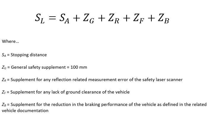
Protective fields should be drawn following manufacturers specifications and SICK provide the following equation with their microScan3 safety laser scanner:
As the value SL increases, the footprint of the industrial autonomous vehicle increases because the scanner needs to see further ahead because of its reaction time. It is advantageous to keep SL as small as possible so that:
• Industrial autonomous vehicles can work in closer proximity to each other
• They do not need large clearance space around them
• Objects and people are less likely to cause stoppages or slow downs of the vehicle
• The vehicles can move much faster with smaller fields and increase availability
This involves investigating each parameter in the control system to optimize the application, figure 6.
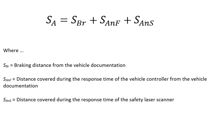
Of all of the parameters listed above, usually the largest value in this chain, and the one that varies the most, is SA, which is the stopping distance of the vehicle. The stopping distance comprises the braking distance for the vehicle, the distance covered during the response time of the safety laser scanner and the response time of the safety control system.
The stopping time comprises the following parameters, see equation:
The braking distance can depend on a number of things such as the type of brakes used, the environment in which the industrial autonomous vehicle is used, the load, direction of travel, state of the wheels etc. and needs careful consideration. The distance covered by the vehicle during the response time of the controller can be improved by looking at the safety control, architecture and connection methods and the distance covered during the response time of the safety laser scanner is dependent on the scanner basic response time of the Scanner used plus how it is configured.
Distance covered during the response of the safety laser scanner
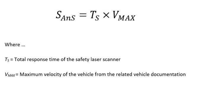
The distance covered during the response time of the safety laser scanner depends on:
• The basic response time of the safety laser scanner
• The maximum velocity of the vehicle
• The additional response time supplements due to multiple sampling settings, transmission times and case switching
This can be seen in the equation below:
It would be impossible to appraise every different environment, industrial autonomous vehicle system, safety controller, scanner and its connections and the value would need to be derived from test data. However, it can be seen that if the scanner has a fast response and the multiple sampling can be kept low then this has a direct influence on the total response time of the system directly affecting the size of the protective field required. In practice, this can equate to differences in the protective field of up to and above 10 M in some cases. What is also important is the transmission times to the control system are kept low. This can be improved in a number of ways such as hard wiring OSSD’s to inputs on safety controllers or using safe communication with "simultaneous field evaluation" to monitor multiple protective fields at the same time.
Conclusion: the perfect size of the protective field
The protective field needs to be suitable for the application but on mobile applications it is advantageous to keep it as small as possible due to the problem of false tripping and the vehicles footprint. Therefore, the response time of the scanner and the total system should be considered. Multiple scans can add to the scanner response time and it is important to know how much of a supplement is required every time an extra scan is added. The more robust and reliable the detection principle of a scanner is means that it is likely that fewer multiple scans will be required in tough environments. This allows vehicle to work at faster speeds, in closer proximity to surrounding contours increasing overall productivity and efficiency and reducing the footprint of installations. The control system that a scanner is connected to and how it is connected should also be considered and simultaneous field evaluation in complex applications or hard wiring in simple applications can improve response times. The maximum size protective field a safety laser scanner can facilitate is an important feature but for industrial autonomous vehicle applications it is more important to look at the total response time and detection robustness so that protective fields can be kept as small as possible whilst being as large as required.
Read more
High-tech integration: innovative sensor technology for mobile robots
Martin Kidman
Product Specialist Machinery Safety SICK (UK) Ltd.
Martin Kidman gained his Ph.D. at the University of Liverpool in 2010 and has been involved in Industrial Automation since 2006 working for various manufacturers of sensors. He has been at SICK UK Ltd. since 2013 as a product specialist for machinery safety providing services, support and consultancy for industrial safety applications. He is also a certified Functional Safety Engineer (TUV Rheinland, #13017/16).
